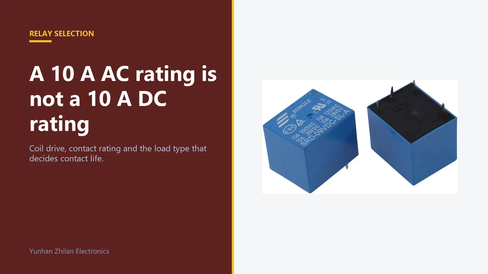
Relays are the component most often chosen by looking at a single number. Engineers read "10 A" on the datasheet, compare it with the load current, and stop there. That number is usually quoted for a resistive AC load, and most real loads are neither resistive nor AC.
This guide covers the four decisions that actually determine whether a relay survives: the coil, the contact rating in context, the load type, and the interface.
Step one: the coil
The coil is an electromagnet with a defined operating voltage and a defined resistance. From those two numbers come the coil current and the coil power, and those decide what drives it.
A 12 V coil with 400 Ω resistance draws 30 mA and dissipates 360 mW. That is comfortably within the capability of an ordinary small-signal transistor. A 12 V coil with 100 Ω draws 120 mA and dissipates 1.44 W, which needs a driver rated for it and a board layout that can carry the current.
- Coil voltage tolerance. Most coils are specified at a nominal voltage with a pull-in threshold well below it and a release threshold well below that. In a 24 V industrial system, a 24 V coil sees 26 V or more when the supply is at its upper tolerance. Check the maximum, not just the nominal.
- Drive current. Add the coil current to whatever else the driver handles. Do not forget that many small relays are driven directly from a logic output with inadequate current capability.
- The flyback diode. Every DC coil needs one. Without it, the collapse of the coil field produces a voltage spike that will eventually destroy the driver or generate enough noise to disrupt the rest of the board.
- Pick-up time and release time. Typically a few milliseconds to ten or more milliseconds. If the application requires faster switching, a relay is the wrong component.
Representative parts: Songle SRD-SL-A series and Songle SRD-SL-C series for general-purpose PCB use, OMRON MY series for socket-mounted industrial panels, and Schneider 8-pin interface relays where wiring and service access matter.
Step two: read the contact rating correctly
A contact rating is not one number. It is a set of numbers, each valid only under the conditions stated next to it. The conditions that matter most are the load type, the voltage, and whether the current is AC or DC.
| Rating stated on the datasheet | What it means | What to check before using it |
|---|---|---|
| 10 A 250 VAC | Maximum current for an AC resistive load at 250 V | Whether your load is genuinely resistive and genuinely AC |
| 10 A 30 VDC | Maximum current for a DC resistive load at 30 V | The DC figure is usually much lower than the AC figure for the same relay |
| 1/2 HP 250 VAC | Motor rating, covers the inrush of a small motor | Whether the motor's locked-rotor current exceeds the test condition |
| TV-5 or TV-8 | Television and similar inrush rating | Useful reference for lamp and capacitive inrush |
| Minimum permissible load | The smallest load for which reliable contact is guaranteed | Low-level signal switching may need a different contact material entirely |
The gap between the AC rating and the DC rating of the same relay is the single most common cause of premature relay failure. A relay rated 10 A at 250 VAC may be rated only 1 A to 3 A at 30 VDC, because a DC arc does not self-extinguish at the zero crossing.
Step three: the load is not what the label says
Inrush current
Incandescent lamps draw five to fifteen times their steady current for the first few milliseconds while the filament is cold. Motors draw five to ten times rated current at start. Capacitive input power supplies can draw even more. The relay contact must survive that first instant, because that is when contact welding happens.
If the inrush is high, either choose a relay with an appropriate inrush rating, add an inrush limiter such as an NTC thermistor, or switch the load with a solid-state device and use the relay only for isolation.
Inductive loads
Solenoids, contactor coils and motor windings store energy in a magnetic field. When the contact opens, that energy produces an arc that erodes the contact surface and can weld it closed. Contact life with an inductive DC load can be a small fraction of the resistive rating.
The practical countermeasures are a flyback diode across a DC coil, an RC snubber across an AC load, and choosing a relay whose datasheet explicitly gives an inductive load rating. Derating the contact current by half is a reasonable starting assumption when no better data is available.
Low-level loads
Switching a few milliamps at a few volts is a different problem. Ordinary silver contacts develop an oxide film that a very small current cannot break through, and the contact becomes intermittently open. For signal-level switching choose gold-plated or gold-flashed contacts, and check the minimum permissible load on the datasheet rather than assuming it will work.
Step four: contact arrangement and configuration
| Configuration | Meaning | Typical use |
|---|---|---|
| SPST-NO | Single pole, single throw, normally open | Simple on and off switching |
| SPST-NC | Single pole, single throw, normally closed | Fail-safe or default-on circuits |
| SPDT / Form C | Single pole, changeover | Selecting between two circuits; also gives a normally closed contact for status feedback |
| DPDT | Two changeover poles | Switching both live and neutral, or two independent circuits |
| 4PDT | Four changeover poles | Interface relays carrying multiple signals from one control output |
Also check whether the contact is single-break or double-break, and whether the relay is sealed or open. Sealed relays tolerate dusty and humid environments; open relays are cheaper but need a clean enclosure.
Interface relays and sockets
In industrial control cabinets, the interface relay on a plug-in socket is the standard solution, and for good reason. The socket gives a mechanical connection that can be replaced without soldering, the relay can be swapped in seconds during a fault, and the same socket accepts relays from several manufacturers.
- Pin count and layout. 8-pin and 14-pin round-pin sockets are the common standards, and blade-style sockets are also widely used. Match the socket to the relay, and check the pin-out rather than assuming the pin count is enough.
- Socket current rating. The socket carries the contact current too. A socket rated lower than the relay defeats the purpose.
- Retention clip. Vibration loosens plug-in relays. Use the clip.
- Status indication. A mechanical flag or an LED indicator saves a great deal of diagnostic time in the field.
- Spare strategy. Using one relay family across a cabinet reduces the number of spare part numbers you must stock.
Selection checklist
- List the coil voltage, the maximum supply voltage, and the available drive current.
- Classify the load: resistive, inductive, capacitive, lamp, motor, or signal level.
- Find the contact rating for that load type at the actual operating voltage, and check whether it is AC or DC.
- Estimate the inrush current and compare it with any inrush or motor rating on the datasheet.
- Choose the contact configuration: NO, NC, changeover, or multiple poles.
- Choose the contact material: silver alloy for power loads, gold for signal loads.
- Decide between a PCB relay and a plug-in relay on a socket.
- Confirm the operating temperature range, the expected mechanical life and the electrical life at your load.
- Plan the flyback diode, snubber or inrush limiter as part of the design, not as a fix later.
How we can help
Send us the load description rather than just the current: what is being switched, at what voltage, AC or DC, and how often. We will recommend the relay family, the contact arrangement and the socket, and tell you what the realistic contact life will be at your load.
For cabinet builds, send the whole list. Interface relays are usually cheaper and faster to supply as a set with sockets than one part number at a time.


