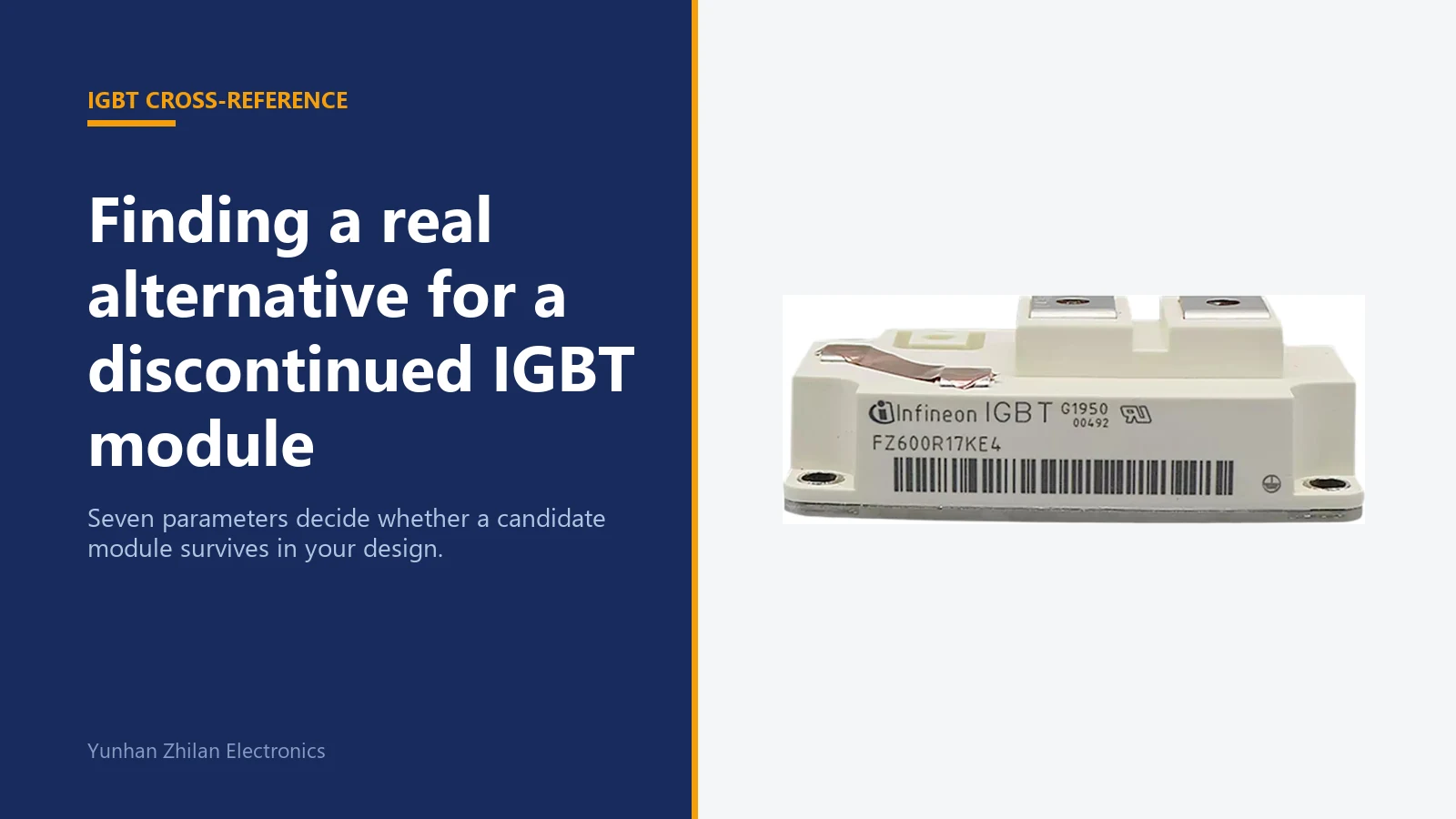
A production line stops, a service engineer needs one module, or a distributor quotes twenty-six weeks. The original IGBT module is discontinued, and somebody has to answer a simple question: what can we put in its place?
Most people start by searching the part number and looking for a datasheet that mentions it. That is the wrong end of the problem. A cross-reference is a compatibility exercise, not a catalogue lookup. This guide sets out the checkpoints that decide whether a candidate module will survive in an existing design.
A cross-reference is only as good as the number of parameters you verify. Two modules with the same voltage and current rating can still destroy each other's gate driver.
What cross-reference actually means
A cross-reference is not a replacement decision. It is a shortlist. The output of a cross-reference exercise is two or three candidate modules that are worth evaluating on a test bench, together with a list of the parameters that did not match exactly.
There are three different situations, and they need different levels of rigour:
- Pure second source. The same die in the same package, from the original manufacturer. Usually a drop-in. Verify the part number suffix, because suffixes encode temperature grade and screening.
- Equivalent module from another manufacturer. Similar ratings, different internal layout. Needs a full parameter comparison and a bench test.
- Functional substitute. A newer module that meets or exceeds the ratings but has a different footprint, different pin-out or different gate charge. This is a redesign, not a replacement.
Only the first case is genuinely drop-in. The second is the normal situation in industrial repair. The third belongs in a design review, not in a maintenance decision.
The seven checkpoints that decide compatibility
1. Topology and circuit configuration
The first check is not electrical, it is architectural. A half-bridge module, a dual common-emitter module, a single switch in a chopper configuration and a six-pack module are not interchangeable even when their ratings match, because the internal connections between the dies are different.
Record the topology from the original datasheet circuit diagram: half-bridge, dual, single switch, chopper, six-pack or PIM. A candidate with a different topology fails immediately, regardless of anything else on this list.
2. Voltage class
Collector-emitter voltage (VCES) sets the ceiling. Moving to a higher voltage class is not automatically safe: a 1700 V module in place of a 1200 V part usually has higher saturation voltage and higher switching losses, which changes the thermal design. Moving to a lower class removes the safety margin entirely.
The practical rule is to match the voltage class exactly, or step up one class only after confirming that the extra losses fit the existing heatsink and that the gate driver still has adequate desaturation protection.
3. Current rating and the temperature it is quoted at
Current ratings on IGBT modules are quoted at a specified case temperature, usually 80 °C or 100 °C. A 600 A rating at 80 °C case is not the same device as a 600 A rating at 25 °C. Always compare at the same reference temperature, and prefer the continuous DC collector current over the pulsed figure.
If the candidate's current rating looks generous but is quoted at a lower case temperature, derate it before comparing. Assuming the heatsink holds the original case temperature is the most common mistake in this step.
4. Saturation voltage and switching losses
Saturation voltage (VCE(sat)) determines conduction loss. Switching energy (Eon, Eoff) determines switching loss. Together they decide whether the module will run hotter than the original, and by how much.
These two numbers frequently move in opposite directions. A module with lower saturation voltage often has slower switching and higher turn-off energy. In a low-frequency application the conduction figure dominates; in a high-frequency application the switching energy dominates. Match the parameter that matters in the actual application.
5. Gate drive compatibility
This is where most otherwise-good cross-references fail. Four things must be checked: the recommended gate-emitter voltage window, the gate charge (Qg) which sets how much drive current the gate driver must supply, the internal gate resistance, and whether the module has an integrated NTC thermistor and at what resistance curve.
A candidate with significantly higher gate charge may exceed the drive capability of the existing gate driver, producing slow switching, high switching loss and eventually thermal failure. A candidate without an NTC, or with a different NTC curve, breaks the over-temperature protection that the inverter firmware relies on.
6. Thermal path
Compare junction-to-case thermal resistance (RthJC) and case-to-heatsink resistance. A module with higher RthJC that is otherwise identical will run hotter at the same current. The baseplate material, thickness and flatness also matter, because they set the quality of the thermal interface to the existing heatsink.
Isolation voltage and creepage distance belong here too. A candidate with lower isolation voltage may be acceptable electrically and unacceptable for the safety certification of the finished machine.
7. Package, footprint and terminal layout
Finally, physical compatibility. The package family (for example 62 mm, EconoDUAL, SEMITRANS, 34 mm), the mounting hole spacing, the terminal positions, the terminal screw or press-fit type and the overall height all have to match the mechanical envelope you already have.
A module that is electrically perfect but 4 mm taller may not fit under the busbar. A module with terminals 5 mm further apart may not reach the laminated busbar without a redesign. Check the mechanical drawing against the original, not against a photograph.
Cross-reference checklist
Use this table during the shortlisting stage. Every row marked as not verified is a risk that has not been eliminated yet.
| Parameter | What to compare | Consequence if it does not match |
|---|---|---|
| Topology | Half-bridge / dual / single switch / chopper / six-pack / PIM | Module cannot be used at all |
| Voltage class | V(CES) rating | Loss of safety margin, or extra losses |
| Current rating | I(C) continuous, at the same case temperature | Overheating under sustained load |
| Saturation voltage | V(CE(sat)) at the application's gate voltage | Higher conduction loss and case temperature |
| Switching energy | E(on), E(off), E(rec) at comparable test conditions | Higher switching loss, derating needed |
| Gate drive | V(GE) window, Q(g), internal R(g) | Slow switching, driver overload, no clean turn-off |
| Temperature sensing | NTC present, resistance curve | Loss of over-temperature protection |
| Thermal resistance | R(thJC), baseplate material and flatness | Runs hotter than the original at equal current |
| Isolation | Isolation voltage, creepage and clearance | Fails machine safety certification |
| Package | Family, footprint, terminal layout, height | Does not fit mechanically |
How the main manufacturer series relate
The four families below cover the majority of industrial repair and MRO demand. They are not formally interchangeable, but the table shows the direction in which engineers normally look when the original is unavailable.
| Family | Typical construction | Common applications | When it is a candidate |
|---|---|---|---|
| Infineon FF series | Half-bridge, 62 mm and EconoDUAL packages | Motor drives, solar inverters, welding | Original design used an Infineon 62 mm half-bridge |
| Semikron SKM series | Half-bridge and dual, SEMITRANS and 62 mm | Drives, UPS, traction auxiliaries | Same voltage and current class in a SEMITRANS footprint |
| Mitsubishi CM series | Dual and half-bridge, 62 mm class | Inverters, servo drives, induction heating | Original was a Mitsubishi dual module |
| Fuji 2MBI series | 2-pack and 6-pack, 62 mm and EconoPACK | General-purpose inverters, pumps, fans | Original was a Fuji 2-pack |
Notice that the packages repeat across manufacturers while the model prefixes do not. That is why a package drawing is often more useful than a model prefix when you are building a shortlist.
A worked example
Suppose the original is a 1200 V, 600 A half-bridge module in a 62 mm package with an integrated NTC, used in a motor drive switching at 8 kHz.
- Confirm the topology. Half-bridge. Any dual or six-pack candidate is eliminated.
- Match the voltage class. 1200 V. A 1700 V candidate is held back unless the extra losses are acceptable.
- Compare current at 80 °C case. Both datasheets quoted at the same reference temperature, so the numbers are directly comparable.
- Compare losses. The candidate has slightly higher saturation voltage but materially lower turn-off energy. At 8 kHz the switching term dominates, so the candidate is likely to run cooler.
- Check the gate drive. The candidate's gate charge is 15% higher. The existing driver is checked against the new figure before proceeding.
- Check the NTC. Present, with a comparable curve. Over-temperature protection still works.
- Check the mechanical drawing. Same hole spacing and terminal positions, 2 mm taller. Clearance under the busbar is verified.
- Bench test. Two samples run at rated current and elevated case temperature, with case temperature and switching waveforms recorded.
Only after step eight does the candidate become a replacement. Steps one to seven produce a shortlist, not an approval.
Where cross-reference goes wrong
- Matching the part number only. Two modules can share a number pattern and differ in internal topology.
- Comparing current ratings from different case temperatures. The comparison silently becomes meaningless.
- Ignoring gate charge. The module switches, the bench test passes at low current, and the failure appears under load months later.
- Assuming the NTC is interchangeable. A different resistance curve feeds a different temperature reading into the firmware's protection logic.
- Skipping the thermal calculation. A 10 °C rise in case temperature can halve the service life of the module and the capacitor bank around it.
- Buying the cheapest quote without traceability. Refurbished and remarked modules appear exactly in this market segment.
How to validate a candidate before a production order
Order two or three samples from one production lot, not from mixed stock. Record the lot code. Run them at rated current with the case temperature held at the same value the original saw in service, and log the case temperature, the collector current and the switching waveforms.
A candidate that reaches thermal equilibrium at a lower case temperature than the original is a good sign. A candidate that stabilises 10 °C or more higher should be re-examined against the derating curves before any volume commitment.
Keep the sample-test record. When the same module is needed again in two years, that record is the difference between a one-day decision and a one-month investigation.
How we can help
Send us the original part number, the nameplate photo of the machine or drive, and the quantity you need. We will come back with the parameters that matter, the candidate modules we can supply, and the points that still need to be verified on your side.
If you are building a spare-parts list rather than replacing a single module, send the whole drive cabinet list. Cross-referencing a cabinet as a set is usually faster and cheaper than dealing with failures one at a time.


